

Ultra-high-power energy buffer. Endless cycling.
Flywheel storage for megawatt charging and weak grids · Built in Europe · DTU Risø Campus, Roskilde
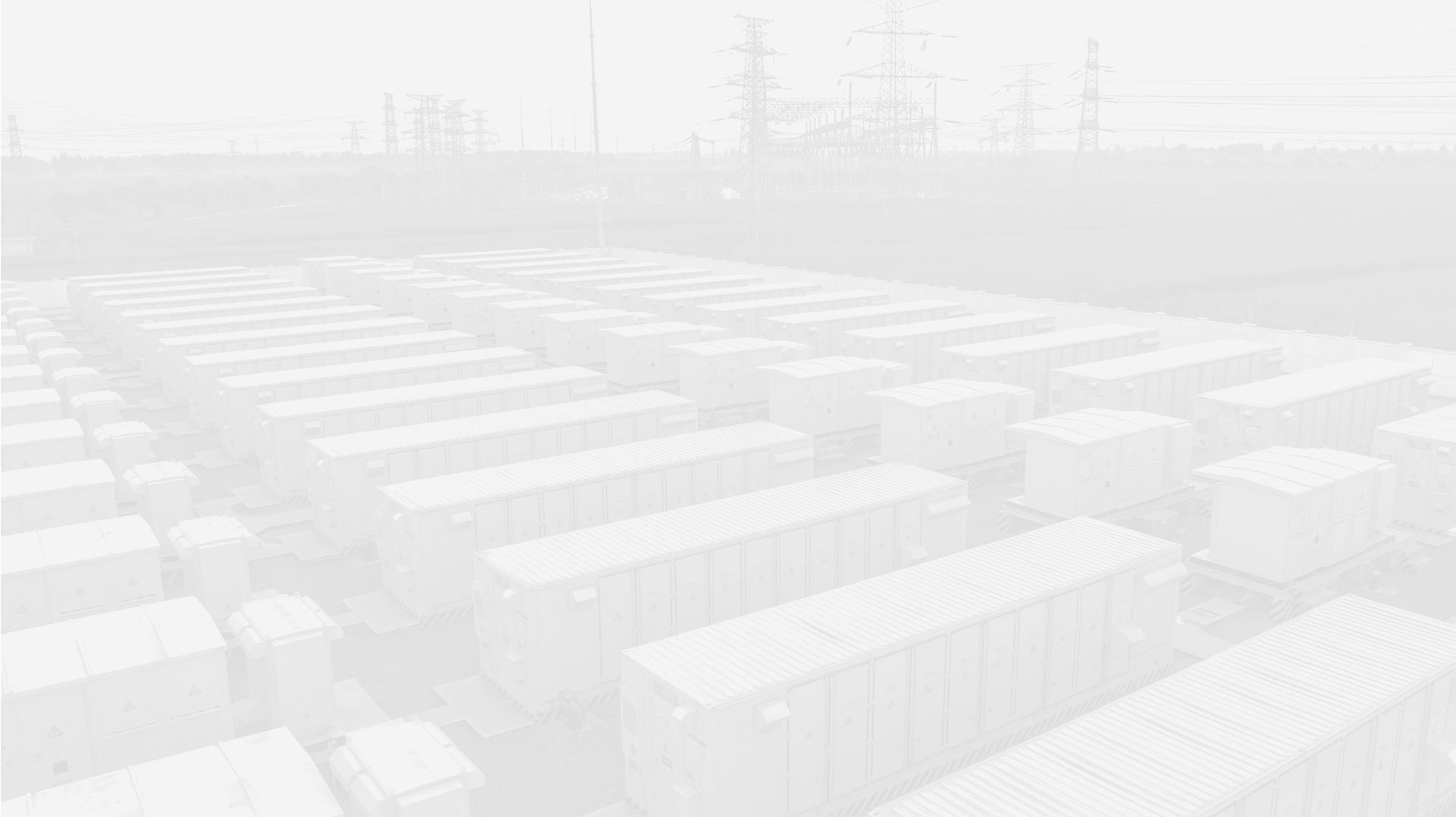
The energy transition can only go as far as energy storage systems take it.
Without adequate storage, surplus renewable generation cannot be absorbed by the grid, causing systemic curtailment of up to 15%
Global energy storage capacity must increase 6X by 2030 to align with net-zero goals
Without sufficient storage, blackout risk increases 100X by 2030 as grids destabilise under high renewable penetration

Heavy cycling wears batteries out.
Every cycle costs capacity
Lithium-ion batteries lose capacity with every charge cycle. In high-cycle duty such as fast charging or grid balancing they degrade fast and need replacing after around 10 years.
Fire risk limits where they go
Thermal runaway risk makes large battery systems harder to permit and place at ports, depots and dense urban sites.
Battery supply chains are dominated by China
Over 90% of the battery value chain is controlled by China – a real risk for Europe's energy security and industrial resilience.
Flywheels: storage that
doesn’t wear out.
Modular, high power
~150 kWh / 500 kW per unit. Combine units to scale to megawatt sites.
Instant response
Under 100 ms – built for charging peaks and grid services.
European supply chain
No lithium or rare earths. A steel rotor and European components for a resilient, independent value chain.
Long lifespan, high efficiency
25 years and 100,000+ cycles with no capacity loss – and high round-trip efficiency that doesn’t fade with age.
Flywheels don’t replace batteries. They take the fast, frequent cycles that wear batteries out.
How it works
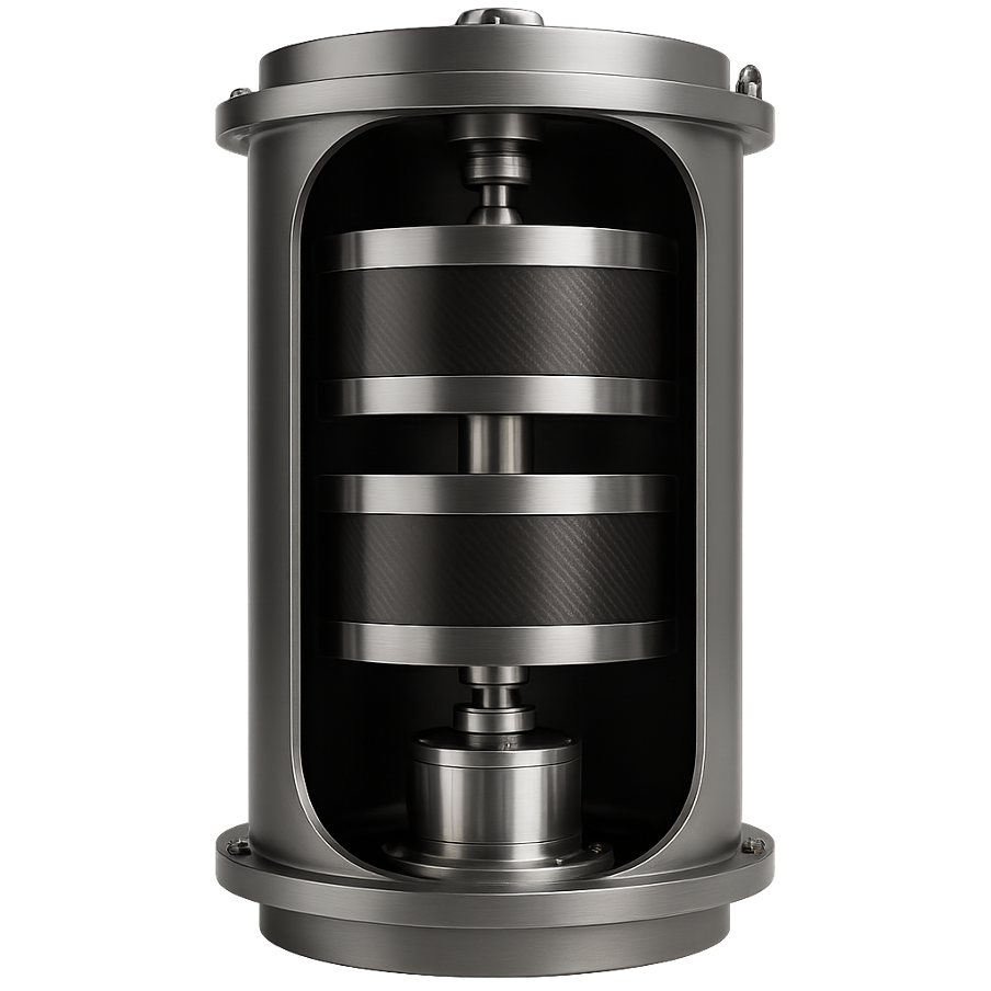
A flywheel stores electricity as kinetic energy in a rotor spinning at high speed. When power is needed, the motor-generator converts the rotor’s momentum back into electricity.
Key principle
Accelerate the rotor → store energy
Decelerate the rotor → deliver energy
Result
Fast response, high efficiency and 100,000+ cycles without wear
Our flywheel combines proven engineering with advanced materials.
Our innovation
We redesigned the traditional flywheel as a mechanical battery, using modern materials.
Optimized with:
Hybrid magnetic bearings → no friction or mechanical wear.
Advanced rotor material:
low-alloy ultra-high-strength steel → high strength, low cost
Stacked sheet-steel rotor → modular and scalable
Result
No mechanical contact. Minimal losses. 25+ year lifetime.
Built for the cycles batteries can’t take.
| Terminus flywheel | Li-ion battery | |
|---|---|---|
| Cycle life | 100,000+ | ~6,000–10,000 |
| Capacity loss | None over 25 years | Lost with every cycle |
| Lifetime | 25 years | ~10 years |
| Efficiency | High – and it stays high | Drops as cells degrade |
| Power | Up to 3C | Typically 0.5–1C |
| Critical materials | None – steel rotor | Lithium, graphite; >90% of value chain in China |
| Fire risk | No thermal runaway | Thermal runaway risk |
No degradation and a 25-year life mean lower cost over the system’s lifetime.
Flywheels and batteries work best side by side: the battery holds the energy, the flywheel takes the cycles.
Where flywheels fit best
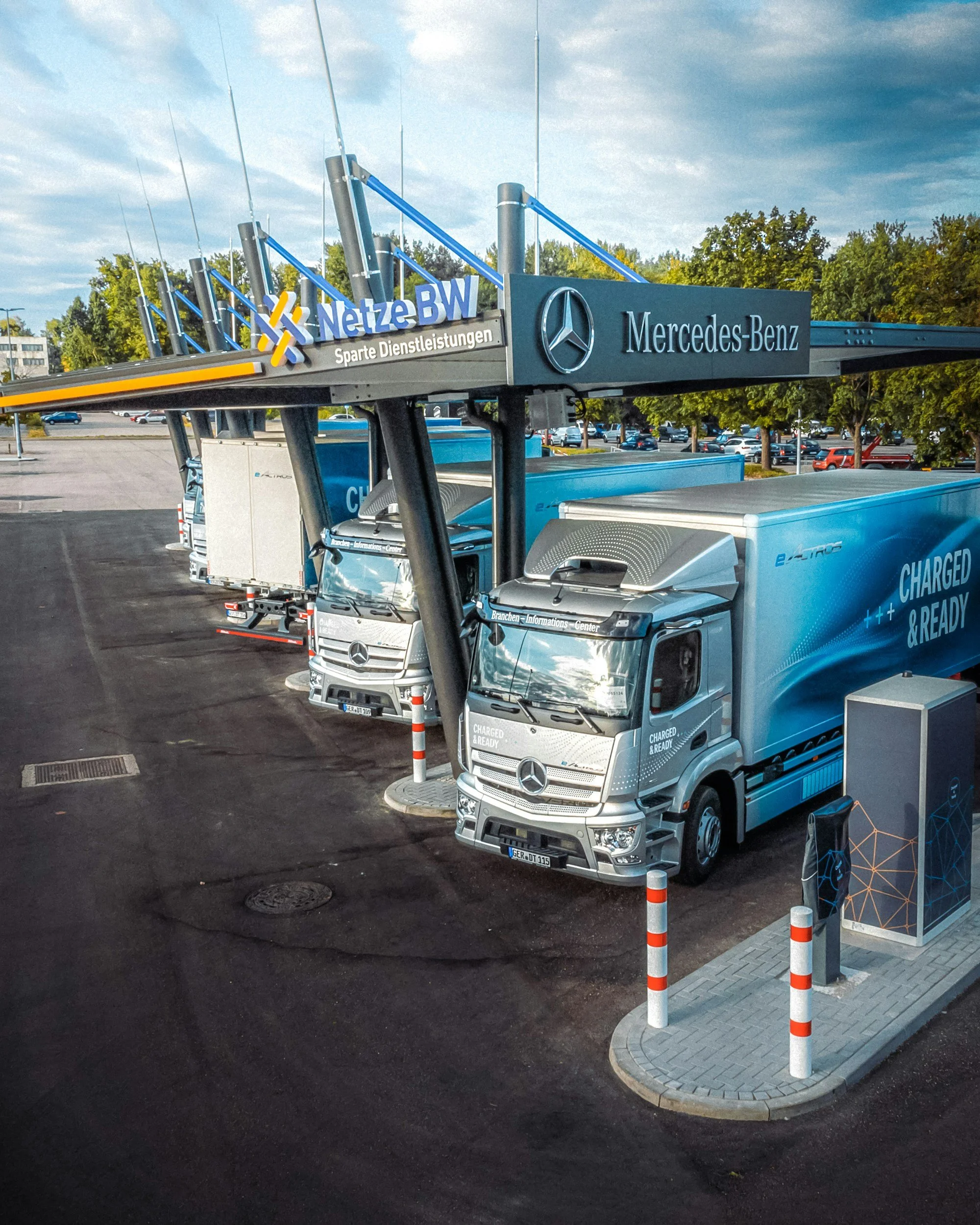
Megawatt charging for e-trucks and EVs
Covers peaks the grid connection can’t deliver
Handles many short, intense sessions without wear

Megawatt charging hubs
Delivers high power from a small grid connection
Go live without waiting years for a grid upgrade
Recharges between sessions from the existing connection
Weak grid connections
Fast balancing and frequency services
Intraday and imbalance trading in DK1 and DK2
Grid services & trading
Testing the critical technology first.
Our Mk1 proof of concept at DTU Risø isolates the hardest part of a flywheel: the magnetic bearing system. A 300 kg sub-scale rotor lets us validate bearing design and control before scaling up. Results from the first bearing stage now feed a redesigned bearing, currently being engineered and simulated.
300 kg
Sub-scale rotor mass
5 axis
Active stabilization
2027
First full-scale prototype
25 yrs
Design lifetime

Terminus test lab — DTU Risø, Roskilde
Hybrid RMB + active TMB — designed from first principles.
-
Hybrid active-passive radial bearing providing contactless rotor suspension. Electromagnetic coils provide active stabilisation with closed-loop control on Teensy 4.1, validated against COMSOL 2D axisymmetric simulation.
-
Active electromagnetic bearing handling axial load support with full closed-loop control — eliminating mechanical contact and wear across all operating conditions.
-
Full active stabilisation of all rotor degrees of freedom across the RMB and TMB — required for contactless suspension of a 300 kg rotor at operating speed.


Our roadmap
2025Founded at DTU. Proof-of-concept rig built at DTU Risø.
2026Innofounder grant from Danmarks Innovationsfond. Magnetic bearing redesign.
2027First full-scale prototype at DTU Risø.
2028Grid-connected pilot at Risø and first high-cycle charging pilot with a customer.
End of 2028First commercial sales.
The team
Stefan Dobrowolski
Co-founder & CEO
Technology, production & IP. Engineering, DTU.
Carl Schwartau
Co-founder & COO
Sales, partnerships & financing. Ex-Bosch Engineering; Technology Entrepreneurship, DTU.
Mikelis Mikelsons
Business Development
Engineering student, DTU.
Adam Flak
Engineering
Engineering student, University of Twente.